“If you can raid the NASCAR parts bin, do it.”
– Dennis Grant
So, in my last entry, I barfed out my thoughts on sway bars for my car. Today’s entry is me actually acting on those thoughts. Today is a step-by-step on how I put a three piece swaybar on my 1987 Grand National.

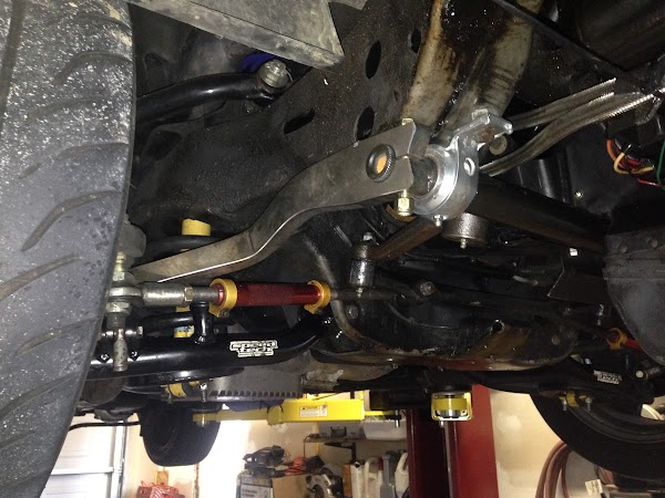
First, the underside as it was. Please pardon what appears to be an oily mess. The car has the factory undercoating on it, and while it currently doesn’t leak, all the previous leaks have turned the undercoating into what can only be described as black slime.
You can see in this picture the stock 32mm conventional swaybar, along with some add on chassis bracing. The diagonal jounce bars you see will be deleted to make room for the new bar.

In this picture, you can see the original sway bar chassis mount, and the 30 year old rubber bushing. The bar is supposed to be able to pivot in this mount as the suspension moves. It didn’t without considerable effort.

And here’s all the old stuff off the car. This is all you have to remove. The bar, mounts, endlinks, and that bracing if you have it.
What I’m installing is no less than a full-on NASCAR road race sway bar setup. Instead of a bent bar mounted in rubber mounts with a sandwiched bushing scheme at the ends, this bar is mounted in brass-raced pillow block bearings, with rod ends connecting the bar to the lower control arms. This setup will eliminate any bind from the crappy rubber bushings sticking and should sharpen steering response since the car will no longer have to wait for bushings to compress before the bar starts to work.
I used a 37.5″ torsion bar from Speedway Engineering. The bar is 1.25″ on the ends, but thickens to 1.5″. This meant the pillow blocks needed to be set a tad wider than the stock mount holes. I also needed to set the bar about an inch forward of the factory bar to clear the idler arm and pitman arms.
The original GM mounts were simply screwed into holes that had been drilled and threaded directly into the frame at the factory. This seems a bit sketch, but if the bar is set up correctly, the body mounts really should not see much load other than holding the assembly to the car. If it was good enough for GM, it was good enough for me. I mocked the bar and pillow blocks in place, and marked the rear mount hole locations.

I then drilled them and tapped them to 3/8-24, and mounted the pillow blocks.

You can see in the picture that the frame slopes upward away from the mount. A spacer had to be made. In my instance, a lug nut ground to the proper angle to sit flush on the frame while also providing a level mount for the pillow block worked perfectly.
The next step is the bar arms. I got mine from Coleman Racing. They’re 49 spline and 17″ long, with a 30 degree bend in the vertical plane. However, to clear the frame and meet up with the end links, they needed to be bent 45 degrees outward. Since these bar arms are 0.75″ thick steel, that was a concern. I considered trying to heat them and bend them with a hand sledge, but that didn’t look like it was going to pan out well. Thus came the only really specialty service required for this install: a 50-ton press.
I got lucky, really. The good folks at RLC Fabrication had a few down minutes and were able to bend these arms for me. Much thanks to them.

Now, this being a non-standard install, it’s important to mock stuff up every single step of the way. Here is one of the bar arms on the end of the swaybar for the first time. It looks great, right?
Wrong. There were issues. First off, the bar arms would hit the steering box bolt heads on the driver side. Shifting the bar over to the driver side to clear the bolt heads rendered the passenger side nearly immobile as it hit the frame on the way up. When you get down to the finished pictures you will see that I flipped the bars side to side. It provided way more frame clearance that way.
Now, after getting the arms in place, I used a piece of baling wire jammed into the rod ends as a sort of variable length end link. I used this to set the end link length, and mark the arm bars for drilling. You want the end links as close to vertical as you can get them at ride height. Once I had an overall length, I cut some threaded rod to fit and assembled the end links. Don’t forget jam nuts!
Once you’ve marked the spot, drill the holes. With metal this thick and tough a drill press is mandatory. Use a lot of cutting oil or you’ll dull the bit. We drilled a small pilot hole, then stepped up to the 3/8″ we needed.

Here’s the end link on the bar arm. Note the spacers. Without them, you lose a lot of articulation range on the rod end.
Now, right at this point is the important part: Make sure you have clearance. Mock it up, and articulate the suspension to make sure nothing hits. If something makes contact while you’re driving around, you will at the very least break something. At the worse, you’ll crash the car. Do not screw around with this step. Don’t save time. Don’t shave corners. Make sure the suspension can cycle through its entire range of motion with the wheels at full steering lock in both directions. If there is any interference anywhere, fix it now.

This is the purty part. We powdercoated the bar arms chrome. I think they came out quite nice. Mirror finish. With a Craftsman powdercoating gun from Sears. How about them apples?

Here’s the driver side snugged in. In the picture, you can see the pillow blocks, the shaft collar used to keep the bar from sliding side to side, the bar arm, and the end link. This photo was taken with the suspension at full droop. Even at full droop with the wheel cranked over to full lock, there is plenty of clearance between the bar arm and the tie rod.

So there you have it. Total install time was about six hours, not including travel time to the store and to get the bar arms bent. I think with all the parts and properly bent bar arms ready to go, I could do this install again in about two hours.
Driving impressions? I’ve only had it around the block, and there is really no way to to test it properly on the street. But what I did get is that the setup is very responsive. It’s also more comfortable. With the new setup, the sway bar is not involved until the car rolls. So hitting expansion joints on the highway? Way better than before. The old bar was definitely binding up. However, street impressions are for naught. The real proof will come a the first event of 2017. During 2016, I was routinely pulling 1 to 1.1 lateral G in the car. It would understeer and wash out quite a bit as the inside front tire came off the ground.
If this bar succeeds in keeping the tires planted, I expect a front end grip improvement that should be measurable. Keep an eye on this space for an update in the spring.
Here’s a photo album with additional photos:
https://goo.gl/photos/enNV6Aki1ppkbELW7
And now, the parts list. I got the actual sway bar, the bar arms, and the pillow blocks from Coleman Racing. Other parts as noted.
1x Speedway 1.25/1.5 Hollow torsion bar, 608-49-150
2x Coleman Racing Products Sway bar arm, steel, 30 degree, 21915
2x Sway bar pillow block bearing, 12328
2x aluminum shaft collar, 1.25″ inner diameter, Amazon.com
1x 12″ fully threaded 3/8-24 rod, McMaster-Carr
2x (for me, you might need 4) Rod end, 3/8-24 female shank, 3/8 ID, McMaster-Carr
4x Steel unthreaded spacer, 3/8 ID, 3/8 length, McMaster-Carr
1x Pack of 4 Grade 9 3/8-16×3 hex head bolt, McMaster-Carr
1x Pack of 10 3/8-16 nylock nuts, McMaster-Carr
There you have it. A big shout out to my Dad for the lift, heated garage, tools, time, and you know, raising me. Also RLC Fabrication for getting me out of a bind with the bar arms; and Coleman Racing Products.